The AVR studio 4 help has a nice picture gallery of the major tools Atmel
makes. In AVR Studio, go to Help--AVR Tools User guide.
The Dragon Board:
I was a bit surprised to find that it takes "User assembly with user parts"
to make it work to any extent for programming parts over the USB port.
Of course, with ZIF sockets costing nearly half of what the entire board costs,
and considering that In System Programming (ISP) is really better, it is understandable
that Atmel let the user populate this part of the board.
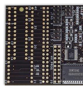
First, the "Prototyping area" is not a prototyping area. It's a pair of socket footprints
for both .300" (up to 28-pin) and .600" (up to 40-pin) parts. Soldering a ZIF socket
is probably a good idea if you want to program parts that aren't installed on a board.
Anyway, there is no socket, so you will have to solder one in be it ZIF or otherwise.
Second, the "Prototyping area" is not connected to anything but a 40-pin .1" DIP header.
That's not installed either, you have to buy one and solder it in.
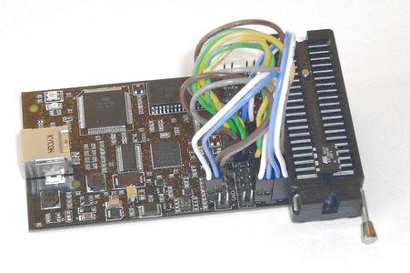
If you want to program parts on the dragon board, you must jumper the 40-pin header
to the programming ports provided on the board.
The prototype area on an out-of-the-box board looks like this:
In this picture, a 40-pin header connector and a
40-pin DIP socket have been soldered on.
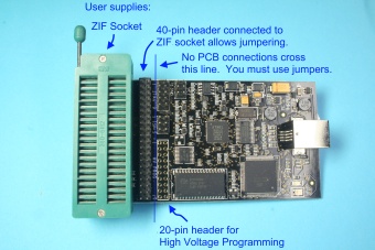
Click image for a 2.3MByte Hi-resolution image.
This picture comes from the help in AVR Studio.
( Go to Help--AVR Tools User Guide--Click on Dragon image--Using the AVR programming area)
A jumpered board.
I have found, however, that if you just solder a 6-pin .1" DIP header on your target
board and connect it into the programming port pins, you can do in-system programming
(ISP) which is by far the most convenient for development.
My advice: The ZIF socket really isn't worth it unless you must program parts
off the board. ISP is the way to go.
